
|
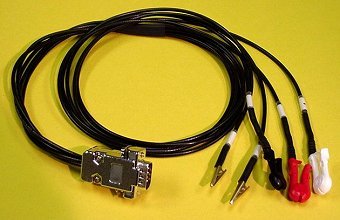
 The AIM-8-V3 uses a shielded five-wire impedance electrode cable assembly for sensing the subjectís bioelectric-impedance and ECG signals. Each of the five wires is a shielded coaxial cable, which prevents the two mA current electrodes from having high frequency cross talk with the impedance detection ECG electrodes. The subject electrode cable assembly is typically 34" long and is terminated with a DB-9 male plug which mates with the corresponding receptacle on the AIM-8-V3 monitor. The electrode lead-wires are numbered 1 through 5 for easy identification. Leads 1 and 4 are the current excitation electrodes and are terminated with spot electrode clips. Lead 5 is also terminated with a spot electrode clip and is used for the Positive ECG spot electrode (note: lead 1 is the negative ECG electrode, and lead 4 is the common electrode). Leads 2 and 3 are the voltage detection electrodes and have alligator clip endings (as can be seen in the picture above) that attach to the band electrodes #2 and #3. Both the Basic and Complete AIM-8-V3 System Packages include one impedance electrode cable assembly. Additional cables may be ordered from BIT as needed. Back to the Complete AIM System Page |